Dime-Sized IMU Sensors

Dime-Sized IMU Sensors

Get the peak of Price & Performace

Talk To Sales
IMU Testing and Implementation Software Inertial Measurement Unit
Talk To Sales

Our IMU Sensor Line-Up

Start with a Development Kit, grow with a Rugged or Dime-Sized Module.

Eval and evb2 sm sq-min

Evaluation Board

This unit contains the IMU sensor and a simple computing board for calculations and easy access interfaces. Test the IMU on your device with this.
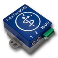
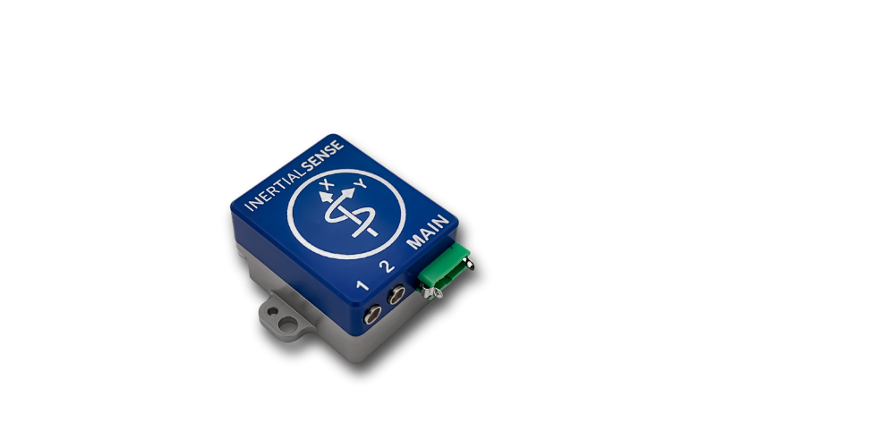
new-rugged-angle-trans-sq-ds-sm-332-min

Rugged IMU 

Built for tough environments. Get accuracy and precision in an aluminum casing. Bulk discounts available.

uINS-3 with dime and rule

IMU Module

The smallest IMU blueprint, at the smallest price. Precision on a module the size of a dime! 

Key Performance Figures

<0.2°
Bias Repeatability
125°C
Temperature Range Calibration

-40°C to 85°C

±2000°/sec
Operating Range
1KHz
Data Rate
>10°/hr
Angular Resolution
1.3
Grams

Detailed Performance And Specifications

Interfacing Communications

Communication Protocols


Module Interface TTL, SPI
Rugged Interface (IS-RUG-1.x) USB, TTL, RS232, RS485, CAN
Max Baud Rate:

  TTL, RS422, RS485

  RS232

Rate:

  3Mbps

  500Kbps

Data Output

  • GPS, GPS Raw, UTC Time
  • IMU (Gyro & Accelerometer)
  • Magnetometer & Barometer
  • Attitude (Quaternions, Euler, DCM)

Sensor Suite

Sensors Gyroscope Accelerometer Magnetometer Pressure
Operating Range ±2000 °/sec ±16 g ±4800 µT 30–120 kPa
Bias Repeatability < 0.2 °/sec < 5 mg    
In-Run Bias Stability < 10 °/hr < 40 μg    
Random Walk 0.15 °/√hr 0.07 m/s/√hr    
Non-linearity 0.2 % FS 0.2 % FS    
Noise Density 0.01 °/s/√Hz 300 μg/√Hz   Pa/√Hz
Bias Error over -40C to 85C
0.7 °/s RMS 0.4 m/s2 RMS    
Max Output Rate 1 KHz 1 KHz 100 Hz 50 Hz
Bandwidth 250 Hz 218 Hz 50 Hz 5 Hz
Alignment Error 0.05° 0.05° 0.05°  
Sampling Rate 8 KHz 4 KHz 100 Hz 250 Hz
Resolution *0.0076 °/sec *122 µg 0.6 µT 0.0016 kPa
*1KHz resolution after oversampling
      (13 cm)

Electrical

Power Draw (w/o GPS ant.) Min Typ Max Units
µIMU @ 1000Hz   340   mW
Supply Voltage (Vcc) 3 3.3 3.6 V
GNSS VBAT Voltage 1.4 3.3 3.6 V
GNSS VBAT Current @ 3.0V   15   µA

GNSS Antenna Supply w/o load

(2.8V w/ 10mA load)*

  2.9    V
GNSS Antenna Supply Current*     300 mA
GNSS Max RF Input Power +15 dBm     +15 dBm
I/O Pin MAX Voltage Range -0.5   3.6 V
Total Output Current, All Pins     120 mA
I/O Pin Input low-level 0.99     V
I/O Pin Input high-level 2.31 3.3 3.6 V
I/O Pin Output high-level   3.3   V
STROBE input frequency     1 KHz
Rising Slope of VIN** 2.4     V/ms

*A 10 Ohm current limiting resistor sits in-line between voltage supply and antenna.

**The supply rising slope must be higher than minimum rating for proper function

Mechanical

Dimensions

SIZE 16.3 x 12.6 x 4.6 mm
WEIGHT 1.3 grams


User Manual & Documentation

Have more questions? Dig into the details with our up-to-date online user manual and full documentation.

View User Manual & Documentation
 

Trusted By The Best

ceres-logo-1@2x (1)
slantrange-light-grey@2x-1.png
Group-16 (1)
Group-17 (1)
Group-18 (1)