Our AHRS Sensor Line-Up
Start with a Development Kit, grow with a Rugged or Dime-Sized Module.

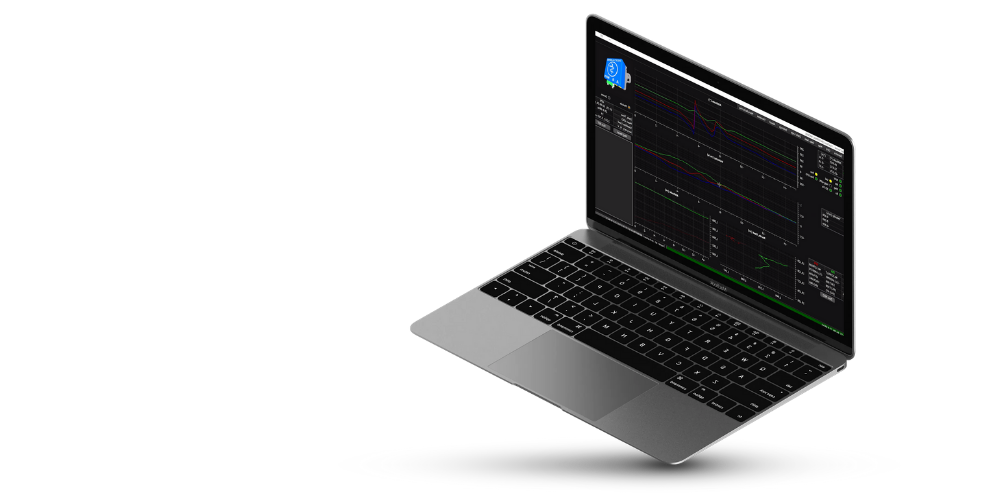
Evaluation Board
This unit contains the AHRS sensor and a simple computing board for calculations and easy access interfaces. Test the AHRS on your device with this.
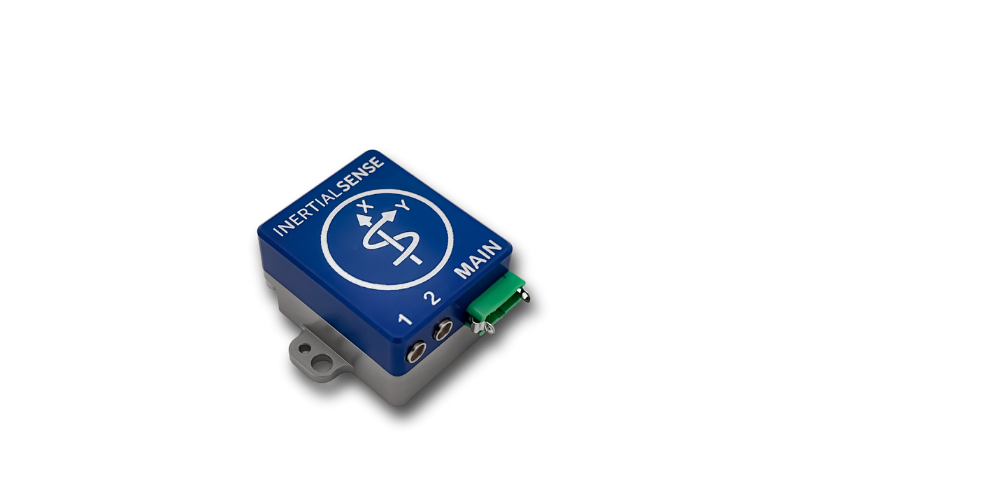
AHRS Module
Our quarter-sized Single or Multi-Band GPS rugged module designed for tough environments. Bulk discounts available.

AHRS Module
The smallest AHRS blueprint, at the smallest price. Accuracy up to 0.05° Angular Resolution in a module the size of a dime!

.png)
.png)
.png)